THE SONOCHEMISTRY CENTRE AT COVENTRY UNIVERSITY
‘The Home of Sound Science’
INTRODUCTION to SONOCHEMISTRY
1. ULTRASOUND
1.1 HISTORICAL BACKGROUND
1.2 THE POWER OF SOUND
1.3 REFERENCES
2. ACOUSTIC CAVITATION
2.1 HOMOGENEOUS LIQUID-PHASE REACTIONS
2.2 CAVITATION NEAR A SURFACE
2.3 HETEROGENEOUS POWDER-LIQUID REACTIONS
2.4 REFERENCES FOR CAVITATION
3.
TRANSDUCERS
3.1
GAS-DRIVEN TRANSDUCERS
3.2
LIQUID-DRIVEN TRANSDUCERS
3.3
ELECTROMECHANICAL TRANSDUCERS
3.3.1
Magnetostrictive Transducers
3.3.2
Piezoelectric Transducers
4. REACTOR DESIGN AND SCALE UP
4.1 Batch Treatment
4.2
Flow Systems
4.3 References
5. EXAMPLES OF RESEARCH
PROJECTS
1. ULTRASOUND
If you were asked what you knew about ultrasound you would almost certainly
start with the fact that it is used in animal communications (e.g. bat
navigation and dog whistles). You might then recall that ultrasound is used in
medicine for foetal imaging, in underwater range finding (SONAR) or in the
non-destructive testing of metals for flaws. A chemist would probably not
consider sound as the type of energy that could be used for the excitation of a
chemical reaction. Indeed up to a few years ago the use of ultrasound in
chemistry was something of a curiosity and the practising chemist could have
been forgiven for not having met the concept. To increase chemical reactivity
one would probably turn towards heat, pressure, light or the use of a catalyst.
And yet, if one stops for a second to consider what is involved in the
transmission of a sound wave through a medium it is perhaps surprising that for
so many years sound was not considered as a potential source of enhancement of
chemical reactivity. The only exception to this being the green-fingered chemist
who, in the privacy of his own laboratory, talks, sings or even shouts at his
reaction. After all, sound is transmitted through a medium as a pressure wave
and the mere act of transmission must cause some excitation in the medium in the
form of enhanced molecular motion. However, as we will see later, in order to
produce real effects the sound energy must be generated within the liquid
itself. This is because the transfer of sound energy from the air into a liquid
is not an efficient process.
1.1 HISTORICAL BACKGROUND
The basis for the present-day generation of ultrasound was established as far
back as 1880 with the discovery of the piezoelectric effect by the Curies [l-3].
Most modern ultrasonic devices rely on transducers (energy converters) which are
composed of piezoelectric material. Such materials respond to the application of
an electrical potential across opposite faces with a small change in dimension.
This is the inverse of the piezoelectric effect. If the potential is alternated
at high frequencies the crystal converts the electrical energy to mechanical
vibration (sound) energy – rather like a loudspeaker. At sufficiently high
alternating potential high frequency sound (ultrasound) will be generated.
The earliest form of an ultrasonic transducer was a whistle developed by Francis
Galton (1822-1911) in 1883 to investigate the threshold frequency of human
hearing [4]. A diagram of the whistle is to be found in the section on
transducers. Galton himself was a remarkable man. As well as inventing the
whistle that carries his name he explored and helped map a portion of the
African interior, invented the weather map and developed the first workable
system for classifying and identifying fingerprints. His whistle was part of his
study of sensory perception, in this case to determine the limits of hearing in
terms of sound frequencies in both humans and animals.
The first commercial application of ultrasonics appeared around 1917 and was the
first “echo-sounder” invented and developed by Paul Langévin (1872-1946). He was
born in Paris and was a contemporary to Marie Curie, Albert Einstein and Hendrik
Lorentz. He was noted for his work on the molecular structure of gases, analysis
of secondary emission of X-rays from metals exposed to radiation and for his
theory of magnetism. However Langévin is more generally remembered for important
work on piezoelectricity and on piezoceramics. The original “echo-sounder”
eventually became underwater SONAR for submarine detection during World War 2.
The transducer was a mosaic of thin quartz crystals glued between two steel
plates (the composite having a resonant frequency of about 50 kHz), mounted in a
housing suitable for submersion. The early "echo sounder" simply sent a pulse of
ultrasound from the keel of a boat to the bottom of the sea from which it was
reflected back to a detector also on the keel. For sound waves, since the
distance traveled through a medium = 1/2 x time x velocity (and the velocity of
sound in seawater is accurately known) the distance to the bottom could be
gauged from the time taken for the signal to return to the boat. If some foreign
object (e.g. a submarine) were to come between the boat and the bottom of the
seabed an echo would be produced from this in advance of the bottom echo. In the
UK this system was very important to the Allied Submarine Detection
Investigation Committee during the war and became popularly known by the acronym
ASDIC. Later developments resulted in a change in the name of the system to
SONAR (SOund Navigation And Ranging) which allowed
the surrounding sea to be scanned. The original ASDIC system predated the
corresponding RAdio Detection And Ranging system
(RADAR) by 30 years.
Essentially all imaging from medical ultrasound to non-destructive testing
relies upon the same pulse-echo type of approach but with considerably refined
electronic hardware. The refinements enable the equipment not only to detect
reflections of the sound wave from the hard, metallic surface of a submarine in
water but also much more subtle changes in the media through which sound passes
(e.g. those between different tissue structures in the body). It is high
frequency ultrasound (in the range 2 to 10 MHz) which is used primarily in this
type of application because by using these much shorter wavelengths it is
possible to detect much smaller areas of phase change i.e. give better
'definition'. The chemical applications of high frequency ultrasound are
concerned essentially with measurements of either the velocity of sound through
a medium or the degree to which the sound is absorbed as it passes through it.
These applications will be discussed in more detail in. Such measurements are
diagnostic in nature and do not effect the chemistry of the system under study.
When more powerful ultrasound at a lower frequency is applied to a system it is
possible to produce chemical changes as a result of acoustically generated
cavitation. Cavitation as a phenomenon was first identified and reported in 1895
by Sir John Thornycroft and Sidney Barnaby [5]. This discovery was the result of
investigations into the inexplicably poor performance of a newly built destroyer
HMS Daring. Her top speed was well below specifications and the problem was
traced to the propeller blades that were incorrectly set and therefore not
generating sufficient thrust. The rapid motion of the blades through water was
found to tear the water structure apart by virtue of simply mechanical action.
The result of this was the production of what are now called cavitation bubbles.
The solution to this problem lies in using very wide blades covering about
two-thirds of the disc area of the propeller, so as to present a very large
surface contact with the water. This helps to prevent disruption under the force
necessary to propel the vessel. As ship speeds increased, however, this became a
serious concern and the Royal Navy commissioned Lord Rayleigh to investigate. He
produced a seminal work in the field of cavitation which confirmed that the
effects were due to the enormous turbulence, heat, and pressure produced when
cavitation bubbles imploded on or near to the propeller surface [6]. In the same
work, he also observed that cavitation and bubble collapse was also the origin
of the noise made when water is heated towards boiling point.
Since l945 an increasing understanding of the phenomenon of cavitation has
developed coupled with significant developments in electronic circuitry and
transducer design (i.e. devices which convert electrical to mechanical signals
and vice versa). As a result of this there has been a rapid expansion in the
application of power ultrasound to chemical processes, a subject which has
become known as “Sonochemistry”.
1.2 T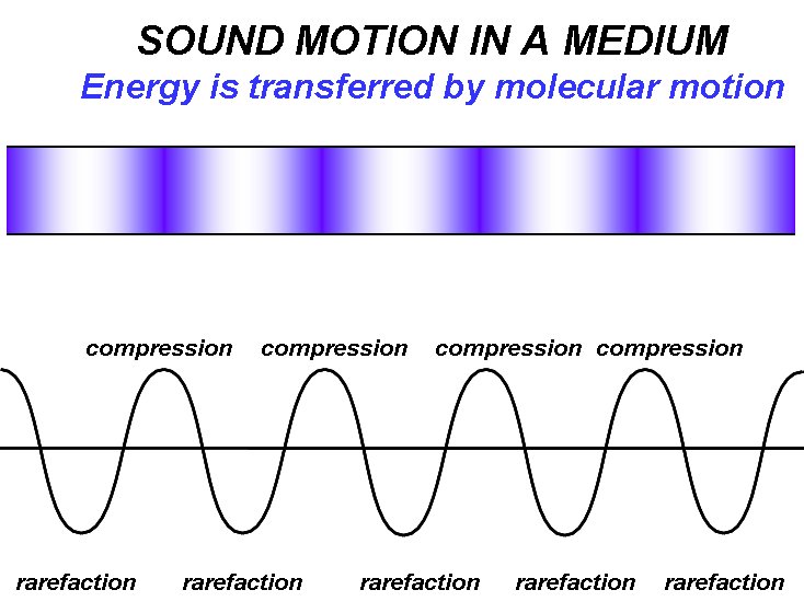 HE
POWER OF SOUND
HE
POWER OF SOUND
Sound,
as a general subject for study, is traditionally found in a physics syllabus but
it is not a topic which is met in a chemistry course and so is somewhat
unfamiliar to practising
chemists. Sound is transmitted through a medium by inducing vibrational motion
of the molecules through which it is travelling. This
motion can be visualised as rather like the ripples produced when a pebble is
dropped into a pool of still water. The waves move but the water molecules which
constitute the wave revert to their normal positions after the wave has passed.
An alternative representation is provided
by the effect of a sudden twitch of the end of a horizontal stretched spring.
Here the vibrational energy is transmitted through the spring as a compression
wave which is seen to traverse its whole length. This is just a single
compression wave and it does not equate to sound itself which
is a whole series of such compression waves separated by rarefaction
(stretching) waves in between. The pitch (or note) of the sound produced by this
series of waves depends upon their frequency i.e. the number of waves which pass
a fixed point in unit time. For middle C this is 256 per second. In physics
sound waves are often shown as a series of vertical lines or shaded colour where
line separation or colour depth represent intensity, or as a sine wave where
intensity is shown by the amplitude (Figure 1.1).
Figure
1.1: Sound transmission
through a medium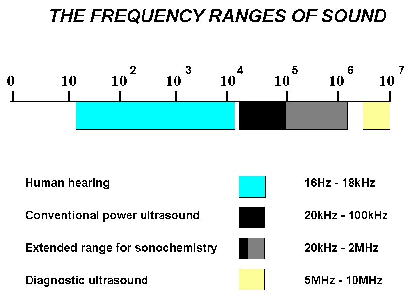
The physical effects of sound vibrations are most easily experienced by standing
in front of a loudspeaker playing music at high volume. The actual sound
vibrations are transmitted through the air and are not only audible but can also
be sensed by the body through the skin. The bass notes are felt through the body
more easily than the high notes and this is connected with the frequency of the
pressure pulse creating the sound. Low frequency sound becomes audible at around
18Hz (1Hz = 1 Hertz = 1 cycle per second) but as the frequency of the sound is
raised (becoming more treble) it becomes more difficult for the body to respond
and that sensation is lost. High frequency sound, while not noticeably effecting
the body does cause severe annoyance to hearing e.g. feed back noise from a
microphone through a loud speaker. At even higher frequencies the ear finds it
difficult to respond and eventually the human hearing threshold is reached,
normally around 18-20kHz for adults, sound beyond this limit is inaudible and is
defined as ultrasound. The hearing threshold is not the same for other animal
species thus dogs respond to ultrasonic whistles (so called "silent" dog
whistles) and bats use frequencies well above 50kHz for navigation (Figure 1.2).
Figure
1.2: Frequency ranges of sound
The broad classification of ultrasound as sound above 20kHz and up to 100MHz can
be subdivided into two distinct regions Power and Diagnostic. The former is
generally at lower frequency end where greater acoustic energy can be generated
to induce cavitation in liquids, the origin of chemical effects. Sonochemistry
normally uses frequencies between 20 and 40kHz simply because this is the range
employed in common laboratory equipment. However since acoustic cavitation in
liquids can be generated well above these frequencies, recent researches into
sonochemistry use a much broader range (Figure 1.2). High frequency ultrasound
from around 5MHz and above does not produce cavitation and this is the range
used in medical imaging.
A whistle which generates a frequency 20kHz is inaudible to humans but perfectly
audible to a dog - and produces no physical harm to either. It is however in the
correct FREQUENCY range to affect chemical reactivity (Power Ultrasound). Yet
such a whistle blown in a laboratory will not influence chemical reactions in
any way. This is because the whistle is producing sound energy in air and
airborne sound cannot be transferred into a liquid.
1.3 REFERENCES
1. A.P.Cracknell, Ultrasonics,
Chapter 6, pp 92-105 (1980) Wykenham Publishers
2. J.Curie and P.Curie, Compt.
Rend. (1880) 91, 294.
3. J.Curie and P.Curie, Compt.
Rend. (1881) 93, 1137.
4. F.Galton, Inquiries into
human faculty and development (1883) MacMillan, London.
5. J.Thornycroft and S.W.Barnaby,
"Torpedo boat destroyers", Proc.Inst.Civil.Engineers (1895) 122, 51
2. ACOUSTIC CAVITATION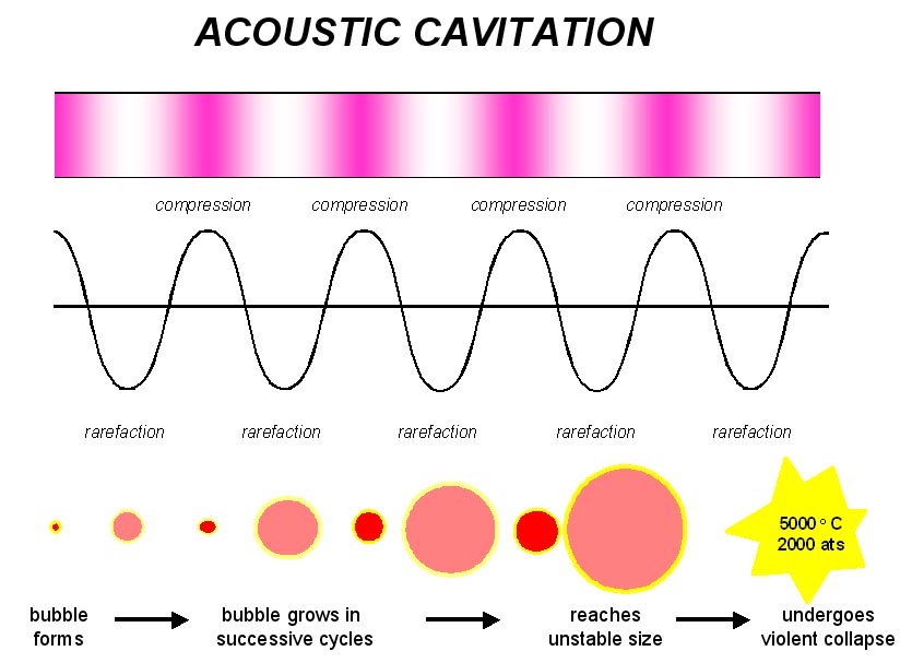
Power ultrasound enhances chemical and physical changes in a liquid medium
through the generation and subsequent destruction of cavitation bubbles. Like
any sound wave ultrasound is propagated via a series of compression and
rarefaction waves induced in the molecules of the medium through which it
passes. At sufficiently high power the rarefaction cycle may exceed the
attractive forces of the molecules of the liquid and cavitation bubbles will
form. Such bubbles grow by a process known as rectified diffusion i.e. small
amounts of vapour (or gas) from the medium enters the bubble during its
expansion phase and is not fully expelled during compression. The bubbles grow
over the period of a few cycles to an equilibrium size for the particular
frequency applied. It is the fate of these bubbles when they collapse in
succeeding compression cycles which generates the energy for chemical and
mechanical effects (Figure 2.1). Cavitation bubble collapse is a remarkable
phenomenon induced throughout the liquid by the power of sound. In aqueous
systems at an ultrasonic frequency of 20kHz each cavitation bubble collapse acts
as a localised "hotspot" generating temperatures of about 4,000 K and pressures
in excess of 1000 atmospheres [1-3].
Figure 2.1: Generation of an acoustic bubble
The cavitation bubble has a variety of effects within the liquid medium
depending upon the type of system in which it is generated. These systems can be
broadly divided into homogeneous liquid, heterogeneous solid/liquid and
heterogeneous liquid/liquid. Within chemical systems these three groupings
represent most processing situations.
2.1 HOMOGENEOUS
LIQUID-PHASE REACTIONS
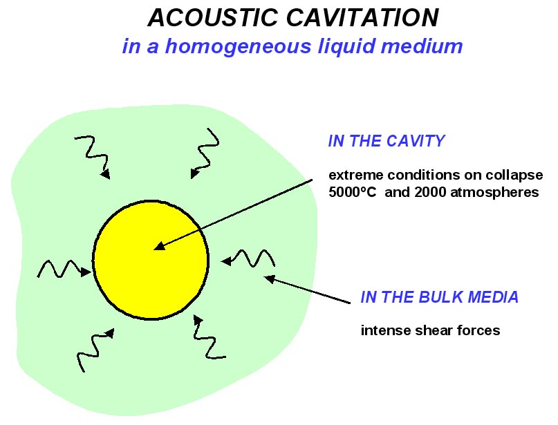
(i) in the bulk liquid immediately
surrounding the bubble where the rapid collapse of the bubble generates shear
forces which can produce mechanical effects and
(ii) in the bubble itself where any species introduced during its formation will
be subjected to extreme conditions of temperature and pressure on collapse
leading to chemical effects. (Figure 2.2).
Figure 2.2: Acoustic cavitation in a homogeneous liquid
2.2 CAVITATION NEAR A SURFACE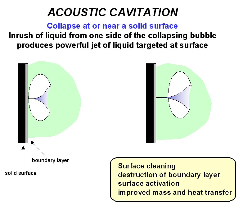
Unlike cavitation bubble collapse in the bulk liquid, collapse of a cavitation
bubble on or near to a surface is unsymmetrical
because the surface provides resistance to liquid flow from that side. The
result is an inrush of liquid predominantly from the side of the bubble remote
from the surface resulting in a powerful liquid jet being formed, targeted at
the surface (Figure 2.3). The effect is equivalent to high pressure jetting and
is the reason that ultrasound is used for cleaning. This effect can also
activate solid catalysts and increase mass and heat transfer to the surface by
disruption of the interfacial boundary layers.
Figure 2.3: Cavitation bubble collapse at or near a solid surface
2.3 HETEROGEN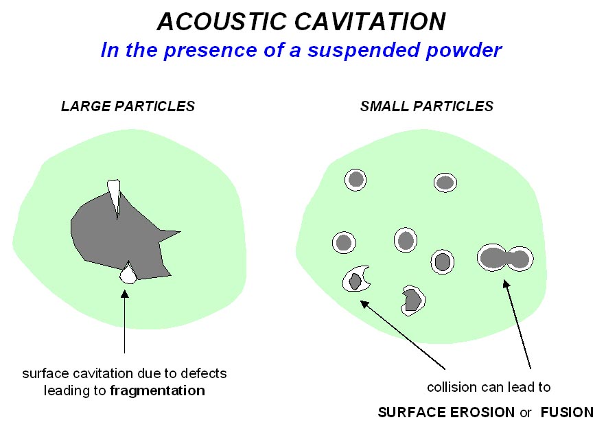 EOUS
POWDER-LIQUID REACTIONS
EOUS
POWDER-LIQUID REACTIONS
Acoustic cavitation can
produce
dramatic effects on powders suspended in a liquid (Figure 2.4). Surface
imperfections or trapped gas can act as the nuclei for cavitation bubble
formation on the surface of a particle and subsequent surface collapse can then
lead to shock waves which break the particle apart. Cavitation bubble collapse
in the liquid phase near to a particle can force it into rapid motion. Under
these circumstances the general dispersive effect is accompanied by
interparticle collisions which can lead to erosion, surface cleaning and wetting
of the particles and particle size reduction.
Figure 2.4: Acoustic cavitation in a liquid with a suspended powder
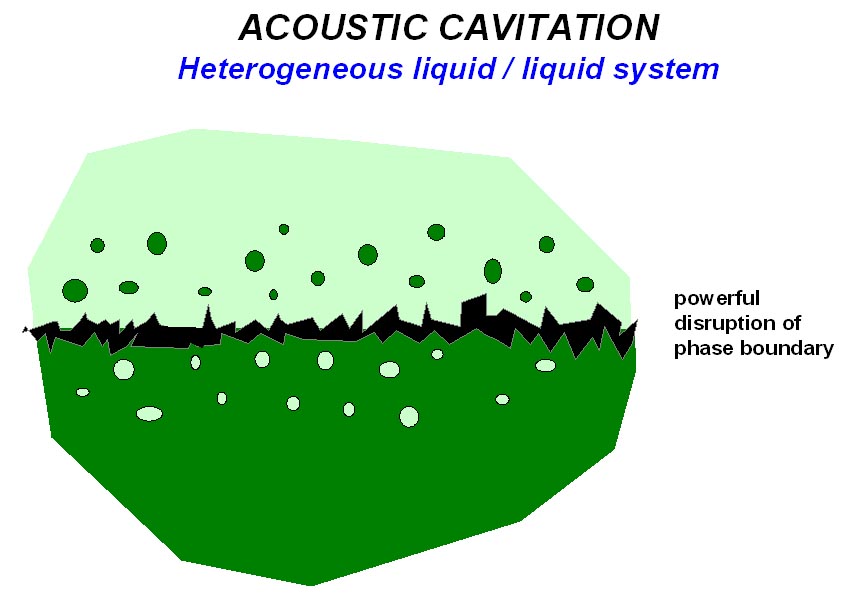
In heterogeneous liquid/liquid reactions, cavitational collapse at or near the
interface will cause disruption
and mixing, resulting in the formation of very fine emulsions (Figure 2.5).
Figure 2.5: Cavitation effects in a heterogeneous liquid/liquid system
2.4 REFERENCES FOR
CAVITATION
1. E.A.Neppiras, Ultrasonics
(1984) 22, 25.
2. A.Henglein, Ultrasonics
(1987) 25, 6.
3. K.S.Suslick, Science (1990)
247, 1439.
3. TRANSDUCERS
A transducer is the name for a device capable of converting one form of energy
into another, a simple example being a loudspeaker which converts electrical
energy to sound energy. Ultrasonic transducers are designed to convert either
mechanical or electrical energy into high frequency sound and there are three
main types: gas driven, liquid driven and electromechanical.
3.1
GAS-D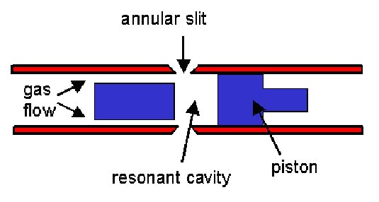 RIVEN
TRANSDUCERS
RIVEN
TRANSDUCERS
These are, quite
simply, whistles
with high frequency output (the dog whistle is a
familiar example). The history of the generation of ultrasound via whistles
dates back
100 years to the work of F.Galton who was interested in establishing the
threshold levels of human hearing. He produced a whistle that generated sound of
known frequencies and was able to determine that the normal limit of human
hearing is around 18kHz. Galton's whistle was constructed from a brass tube with
an internal diameter of about two millimetres (Figure 3.1) and operated by
passing a jet of gas through an orifice into a resonating cavity. On moving the
plunger the size of the cavity could be changed to alter the "pitch" or
frequency of the sound emitted. An adaptation of this early principle is to be
found in some dog whistles that have adjustable pitch.
Figure 3.1: Galton Whistle
An alternative form of gas generated ultrasound is the siren. When a solid
object is passed rapidly back-and-forth across a jet of high pressure gas it
interferes with the gas flow and produces sound of the same frequency at which
the flow is disturbed. A siren can be designed by arranging that the nozzle of a
gas jet impinges on the inner surface of a cylinder through which there are a
series of regularly spaced perforations. When the cylinder is rotated the jet of
gas emerging from the nozzle will rapidly alternate between facing a hole or the
solid surface. The pitch of the sound generated by this device
will depend upon the speed of rotation of the cylinder. Neither type of
transducer has any significant chemical application since the efficient transfer
of acoustic energy from a gas to a liquid is not possible. However whistles are
used for the atomization of liquids.
The conventional method of producing an atomized spray from a liquid is to force
it at high velocity through a small aperture. (A typical domestic examples being
a spray mist bottle for
perfume). The disadvantage in the design of conventional equipment is that the
requirement for a high liquid velocity and a small orifice restricts its usage
to low viscosity liquids and these atomizers are often subject to blockage at
the orifice.
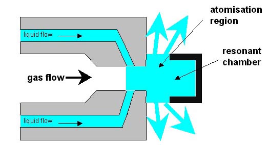
Figure 3.2 shows a schematic gas driven atomizer. The system comprises of an air
or gas jet, which is forced into an orifice where it expands and produces a
shock wave. The result is an intense field of sonic energy focused between the
nozzle body and the resonator gap. When liquid is introduced into this region it
is vigorously sheared into droplets by the acoustic field. Air by-passing the
resonator carries the atomized droplets downstream in a fine soft plume shaped
spray. The droplets produced are small and have a low forward velocity. Atomized
water sprays have many uses
including dust suppression in industry and humidifiers for horticultural use
under glass.
Figure 3.2: Gas Driven Atomizer
3.2
LIQUID-DRIVEN TRANSDUCERS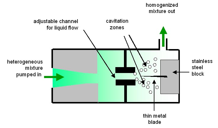
In essence this type of transducer is a "liquid whistle" and generates
cavitation via the motion of a liquid rather
than a gas. Process material is forced at high velocity by the homogeniser pump
through a special orifice from which it emerges as a jet which impacts
upon a steel blade (Figure 3.3). There are two ways in which cavitational mixing
can occur at this point. Firstly through the Venturi effect as the liquid
rapidly expands into a larger volume on exiting the orifice and secondly via the
blade which is caused to vibrate by the process material flowing over it. The
relationship between orifice and blade is critically controlled to optimise
blade activity. The required operating pressure and throughput is determined by
the use of different sizes and shapes of the orifices and the velocity can be
changed to achieve the necessary particle size or degree of dispersion. With no
moving parts, other than a pump, the system is rugged and durable. When a
mixture of immiscible liquids is forced through the orifice and across the blade
cavitational mixing produces extremely efficient homogenization.
Figure
3.3: Liquid Whistle
3.3
ELECTROMECHANICAL TRANSDUCERS
The two main types of electromechanical transducers are based on either the
piezoelectric or the magnetostrictive effect. The most commonly used of which
are piezoelectric transducers, generally employed to power the bath and probe
type sonicator systems. Although more expensive than mechanical transducers,
electromechanical
transducers are by far the most versatile.
3.3.1
Magnetostrictive Tr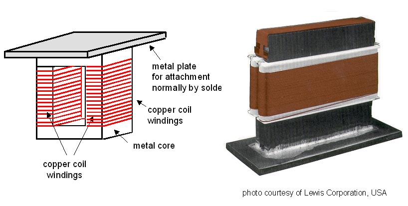 ansducers
Historically magnetostrictive transducers were the first to be used on an
industrial scale to generate high power ultrasound. These are devices which use
an effect found in some materials e.g. nickel which reduce in size when placed
in a magnetic field and return to normal dimensions when the field is removed (magnetostriction).
When the magnetic field is applied as a series of short pulses to a
magnetostrictive material it vibrates at the same frequency. In simple terms
such a transducer can be thought of as a solenoid in which the magnetostrictive
material (normally a laminated metal or alloy) forms the core with copper wire
winding. To avoid magnetic losses two such solenoids are wound and connected in
a loop (Figure 3.4).
Figure 3.4: Piezoelectric Sandwich Transducer
The major advantages of magnetostrictive systems are that they are of an
extremely robust and durable construction and provide very large driving forces.
This makes them an attractive proposition for heavy duty industrial processing.
There are however two disadvantages, firstly the upper limit to the frequency
range is 100kHz, beyond which the metal cannot respond fast enough to the
magnetostrictive effect, and secondly the electrical efficiency is less than 60%
with significant losses emerging as heat. As a result of the second of these
problems all magnetostrictive transducers subject to extended use are liquid
cooled. This has meant that piezoelectric transducers (see below) which are more
efficient and operate over a wider frequency range are generally considered to
be the better choice in sonochemistry, especially in laboratory situations.
However now that a range of industrial applications for sonochemistry are under
consideration, particularly those requiring heavy duty continuous usage at high
operating temperatures, the magnetostrictive transducer is coming back into
consideration.
Many improvements in the operating efficiency of this type of transducer have
been made all of which are based on finding a more efficient magnetostrictive
core. The original nickel based alloys have been replaced by more electrically
efficient cobalt/iron combinations and, more recently, aluminium/iron with a
small amount of chromium. One of the latest developments in magnetostrictive
technology has been the introduction of a new material called TERFINOL-D. This
is an alloy of the rare earths terbium and dysprosium with iron which is zone
refined to produce a material almost in the form of a single crystal. It can be
produced in various forms, rods, laminates, tubes etc and has several major
advantages over the more conventional alloys used. A magnetostrictive transducer
based on this material can generate more power than a conventional piezoelectric
transducer, it is compact (about 50% smaller) and lighter than other
magnetostrictives. It does have the same problem as other such devices in that
it has an upper limit of frequency response - in this case 70kHz.
3.3.2
Piezoelectric Transducers
The most common types of transducer used for both the generation and detection
of ultrasound employ materials that exhibit the piezoelectric effect, discovered
over a century ago. Such materials have the following two complementary
properties:
1.
The direct effect -
when pressure is applied across the large surfaces of the section a charge is
generated on each face equal in size but of opposite sign. This polarity is
reversed if tension is applied across the surfaces.
2.
The inverse effect - if a charge is applied to one face of the section
and an equal but opposite charge to the other face then the whole section of
crystal will either expand or contract depending on the polarity of the applied
charges. Thus on applying rapidly reversing charges to a piezoelectric material
fluctuations in dimensions will be produced. This effect can be harnessed to
transmit ultrasonic vibrations from the crystal section through whatever medium
with which it is in contact.
Quartz was the piezoelectric material originally used in devices such as the
very early types of ASDIC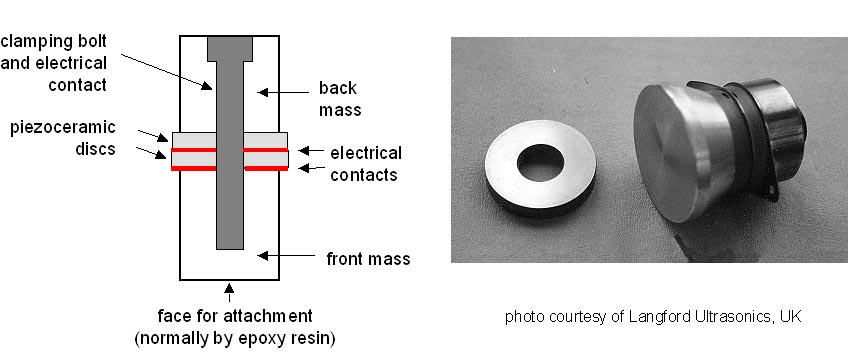 underwater ranging equipment. Quartz is not a particularly good material for
this purpose because of its mechanical properties, it is a somewhat fragile and
difficult to machine. Modern transducers are based on ceramics containing
piezoelectric materials These materials cannot be obtained as large single
crystals and so, instead, they are ground with binders and sintered under
pressure at above 1000oC to form a ceramic. Cooling from above their
ferroelectric transition temperature in a magnetic field then aligns the
crystallites of the ceramic. Such transducers can be produced in different
shapes and sizes. Nowadays the most frequently employed piezoceramic contains
lead zirconate titanate (commonly referred to as PZT where the P represents
plumbum - the chemical term for the element lead - and the Z and T are initials
from the name of the salts).
underwater ranging equipment. Quartz is not a particularly good material for
this purpose because of its mechanical properties, it is a somewhat fragile and
difficult to machine. Modern transducers are based on ceramics containing
piezoelectric materials These materials cannot be obtained as large single
crystals and so, instead, they are ground with binders and sintered under
pressure at above 1000oC to form a ceramic. Cooling from above their
ferroelectric transition temperature in a magnetic field then aligns the
crystallites of the ceramic. Such transducers can be produced in different
shapes and sizes. Nowadays the most frequently employed piezoceramic contains
lead zirconate titanate (commonly referred to as PZT where the P represents
plumbum - the chemical term for the element lead - and the Z and T are initials
from the name of the salts).
Figure 3.5: Piezo electric Transducer
The most common form is a disk with a central hole. In a power transducer it is
normal practise to clamp two of these piezoelectric disks between metal blocks
which serve both to protect the delicate crystalline material and to prevent it
from overheating by acting as a heat sink. The resulting "sandwich" provides a
durable unit with doubled mechanical effect (Figure 3.5). The unit is generally
one half wavelength long (although multiples of this can be used). The peak to
peak amplitudes generated by such systems are normally of the order of l0-20
microns and they are electrically efficient. Generally piezoelectric devices
must be cooled if they are to be used for long periods at high temperatures
because the ceramic material will degrade under these conditions.
Such transducers are highly efficient (>95%) and, depending on dimensions, can
be used over the whole range of ultrasonic frequencies from 20kHz to many MHz.
They are the exclusive choice in medical scanning which uses frequencies above
5MHz.
4. REACTOR DESIGN AND SCALE UP
The design of
sonochemical reactors and the rationale for the scale up of successful
laboratory ultrasonic experiments are clear goals in sonochemistry and
sonoprocessing. Indeed the progress of sonochemistry in green and
sustainable chemistry is dependent upon the possibility of scaling up the
excellent laboratory results for industrial use. The first step in the
progression of a sonochemical process from laboratory to large scale is to
determine whether the ultrasonic enhancement is the result of a mechanical or a
truly chemical effect. If it is mechanical then ultrasonic pre‑treatment of
slurry may be all that is required before the reacting system is subjected to a
subsequent conventional type reaction. If the effect is truly sonochemical
however then sonication must be provided during the reaction itself. The second
decision to be made is whether the reactor should be of the batch or flow type.
Whichever type is to be used there are only three basic ways in which ultrasonic
energy can be introduced to the reacting medium.
·
Immerse
reactor in a tank of sonicated liquid (e.g. flask dipped into a cleaning
bath)
·
Immerse an
ultrasonic source directly into the reaction medium (e.g. probe placed in a
reaction vessel)
·
Use
reactor constructed with vibrating walls (e.g. a tube operating through
radial vibrations)
4.1 Batch
Treatment
The obvious batch treatment processor is the ultrasonic cleaning
bath which is a readily available source of low intensity ultrasonic irradiation
generally at a frequency of around 40kHz. A reactor based on this design might
require adaptation to provide chemically resistant walls, a sealed lid for work
under an inert atmosphere and mechanical stirring. Using this system for large
volume treatment the acoustic energy entering the reaction would be quite small
and any stirrer and fittings in the bath would cause attenuation of the sound
energy.
An alternative configuration would involve using a submersible
transducer assembly which have been used for many years in the cleaning
industry. It consists of a sealed unit within which transducers are bonded to
the inside of one face and can be designed to fit into any existing reaction
vessel.
4.2 Flow
Systems
Flow Systems are generally regarded as the best approach to
industrial scale sonochemistry. The general arrangement would consist of a flow
loop outside a normal batch reactor which acts as a reservoir within which
conventional chemistry can occur. Such an arrangement allows the ultrasonic dose
of energy entering the reaction to be controlled by transducer power input and
flow rate (residence time). Temperature control is achieved through heat
exchange in the circulating reaction mixture.
Pipes of various
cross‑sectional geometry can be converted to flow processors by generating
ultrasonic vibrations through their walls. The length of pipe must be accurately
designed so that a null point exists at each end and it can then be retro‑fitted
to existing pipework. Such systems are capable of handling high flow rates and
viscous materials. There are four common cross-sectional geometries:
rectangular, pentagonal, hexagonal and circular. The pentagonal pipe provides a
fairly uniform ultrasonic field since the energy from each irradiating face is
reflected at an angle from the two opposite faces. The other configurations
provide a "focus" of energy in the centre where direct energy and that reflected
from the opposite wall meet.
4.3 References
1
Practical
Considerations for Process Optimisation,
by T.J.Mason and E.Cordemans de Meulenaer, Synthetic Organic Sonochemistry,
ed J-L.Luche, Plenum Press, 301-328 (1998).
2
The design of
ultrasonic reactors for environmental remediation,
T J Mason, Advances in Sonochemistry, 6,
Ultrasound in Environmental Protection, ed. T.J.Mason and A.Tiehm, Elsevier,
247-268 (2001).
3
High
Powered Ultrasound in Physical and Chemical Processing,
T.J.Mason, New Acoustics – Selected Topics, eds C.Ranz-Guerra and
J.A.Gallego-Juarez, Biblioteca de Ciecias, 7, Consejo Superior de
Investigaciones Cientificas, 105-138, (2003).
4
A novel angular
geometry for the sonochemical silver recovery process at cylinder electrodes,
B.G. Pollet, J.P. Lorimer, S.S. Phull, T.J. Mason and J.-Y. Hihn,
Ultrasonics Sonochemistry
10, pp 217-222
(2003).
5. EXAMPLES OF RESEARCH PROJECTS
“Prospects for
scale-up in the ultrasonic extraction of natural materials”
“Large scale sonochemical processing”
“Ultrasonic intensification of chemical processing and related
operations”
“Sonic and ultrasonic removal of
chemical contaminants from soil in the laboratory and on a large scale”